
What Are Core Pins and How Do You Source Them?

Core Pins are small components with a major influence on molded-part quality. They form internal holes, bosses, and narrow passages inside an injection mold. Their diameter, length, hardness, surface finish, and cooling behavior can affect flash, sticking, warpage, and cycle time. A poor selection may leave marks inside a cavity. It may also create costly downtime.

Industry data shows why this detail matters. Grand View Research’s Injection Molded Plastics Market report identifies strong demand for precision plastic components across automotive, medical, electronics, and consumer products. Mordor Intelligence’s Injection Molding Market analysis also highlights automation, tighter tolerances, and shorter production cycles as continuing priorities. These reports do not isolate Core Pins as a separate market. That limitation deserves attention. Still, their findings explain why reliable mold components matter.

John Bozzelli, an injection molding consultant and founder of Injection Mold Consulting, has stated, “The mold is the heart of the process.” His point applies directly here. Core Pins are not interchangeable steel rods. Material grade, heat treatment, fit, venting, and supplier consistency all deserve review. Experienced mold builders often compare a drawing with the actual molding conditions, including resin shrinkage and ejection loads. That practical step is easy to skip.

This guide explains how Core Pins work and how to source them with greater confidence. It covers specifications, supplier evaluation, quality documents, lead times, and inspection points. A catalog number may look precise. It may still hide a weakness. The best sourcing decision balances dimensional accuracy, service life, availability, and total production risk.
What Are Core Pins and How Do You Source Them?

Core Pins: Definition and Role in Injection Molding

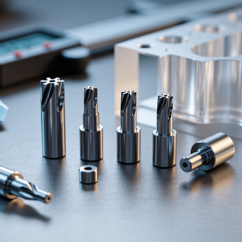
A core pin is a precision cylindrical insert used inside an injection mold. It forms a hole, recess, or internal passage in the molded part. During injection, molten polymer flows around the pin. After cooling, the pin separates from the finished component. Its diameter, straightness, and surface finish directly influence part accuracy. A small error can create flash, sticking, or an undersized opening. Core pins may be fixed, replaceable, stepped, or shaped for special geometries. They are often made from hardened tool steel or other wear-resistant materials. Material selection depends on resin abrasiveness, molding temperature, production volume, and corrosion risk. A pin is not just a metal rod.

In a well-maintained mold, the core pin supports repeatable part production. Proper clearance allows smooth ejection without excessive resin leakage. Good alignment also reduces bending, wear, and premature breakage. Cooling conditions matter when the pin transfers heat from thin internal features. However, design decisions are not always perfect. A longer pin may improve geometry but increase deflection risk. A harder material may extend service life but raise machining costs. Testing the actual resin and molding cycle remains valuable.

When sourcing core pins, provide a detailed drawing, material requirement, hardness range, tolerance, surface finish, and quantity. Include the mold steel and expected production volume. Ask the supplier about inspection records and dimensional measurement methods. Critical dimensions should receive documented verification. Sample pins can expose problems before full production begins. Check the fit in the mold, not only the certificate. This practical step is easy to miss. Reliable sourcing depends on communication, traceability, and realistic tolerances. A cheap pin that causes repeated downtime is rarely economical.

Common Core Pin Types and Their Structural Differences

What Are Core Pins and How Do You Source Them?

Core pins form internal holes, slots, and narrow cavities in injection-molded parts. Their structure directly affects accuracy, cooling, and service life. Straight core pins have a constant diameter and suit simple through-holes. Stepped pins combine two or more diameters, controlling wall thickness across different sections. They reduce material stress, but their shoulders need precise transitions.

Replaceable core pins use a separate pin and holder. This design lowers maintenance costs when wear concentrates near the cavity surface. Headed pins resist axial movement during molding. Vented pins include small gas-release paths, helping reduce burn marks in deep cavities. Blade pins create thin rectangular openings, but they are more sensitive to bending. Collapsible cores add moving segments for complex internal shapes. Their mechanics are effective, though costly and harder to inspect.

Market pressure makes these choices more important. Fortune Business Insights reported that the global injection molding machine market reached 15.79 billion U.S. dollars in 2022, with projected growth to 21.54 billion by 2029. Grand View Research also identified rising demand for precision molding equipment in automotive and medical applications. These figures do not measure core pins directly, but they show expanding demand for stable tooling. In sourcing, compare pin material, hardness, straightness, surface finish, and replacement tolerance. A cheaper pin can fail quickly under repeated thermal cycling. That mistake is easy to make. Designers should also request inspection records and sample measurements, because catalog dimensions alone rarely reveal real production consistency.

What Are Core Pins and How Do You Source Them?

Common core pin types and their structural differences

This chart compares typical structural features used to classify core pin designs. A value of 1 indicates that the feature is characteristic of the pin type, while 0 indicates that it is generally absent. Actual geometry, materials, tolerances, coatings, and cooling details should be selected according to the mold design and production requirements.

Key Specifications for Choosing the Right Core Pins

Core pins are precision mold components that form holes, recesses, or internal features in molded parts. Their dimensions directly affect part accuracy and tool life.

Diameter is the first specification to verify. Even a small mismatch can create flash, sticking, or uneven wall thickness. Specify the diameter tolerance, overall length, working length, and shoulder dimensions. The pin must fit the mold plate without excessive movement. Measure the mating bore instead of trusting an old drawing.

Material selection depends on production volume, resin type, temperature, and wear risk. Hardened tool steel suits demanding cycles, while stainless options may help in corrosive environments. Confirm hardness after heat treatment. A hard surface can still fail if the core is poorly supported. Surface finish also matters, especially when the molded part releases around the pin. Polished surfaces reduce drag, but excessive polishing may change the intended size.

Check straightness, concentricity, and tip geometry before ordering. Cooling requirements deserve attention for long or heavily heated pins. Ask the supplier for inspection records, material certificates, and dimensional reports. Request sample pieces when the tolerance is tight. In practice, sourcing decisions often focus too much on price. That is a mistake. Lead time, replacement consistency, and technical communication can matter more during production. I would also review the drawing once more before approval. Small assumptions are easy to miss.

What Are Core Pins and How Do You Source Them? - Key Specifications for Choosing the Right Core Pins

Specification / Sourcing Dimension Typical Options or Values Why It Matters Recommended Selection Guidance
Core pin function Forms internal holes, cavities, slots, bosses, and other negative features in an injection-molded or die-cast part. The pin geometry directly affects the finished part's dimensions, appearance, and ejection behavior. Define the required molded feature first, then specify the pin's diameter, length, tip geometry, and fit.
Common material Hardened tool steel; pre-hardened alloy steel; corrosion-resistant stainless tool steel for demanding environments. Material determines wear resistance, toughness, corrosion resistance, thermal stability, and service life. Use hardened steel for abrasive or high-volume molding; consider corrosion-resistant steel when moisture, corrosive resin, or frequent cleaning is expected.
Hardness Common hardened tool-steel core pins are often specified around 45–60 HRC, depending on steel grade and application. Higher hardness generally improves wear resistance but may reduce toughness and increase sensitivity to impact or improper handling. Match the hardness to resin abrasiveness, production volume, operating temperature, and risk of side loading.
Nominal diameter Select from the required molded-hole size and the available standard or custom diameter range. Diameter controls the final feature size and influences buckling resistance, heat transfer, and pin strength. Specify finished diameter, allowable tolerance, measurement temperature, and whether the dimension is before or after coating.
Diameter tolerance Typical precision-ground pin tolerances may range from approximately ±0.005 mm to ±0.02 mm, depending on size and supplier capability. The pin tolerance contributes to the dimensional accuracy of the molded feature and the clearance in the mold. Use the tightest practical tolerance; verify the required mold fit rather than specifying unnecessarily expensive precision.
Overall length Determined by the mold stack, cavity depth, support arrangement, and required retention length. An unsuitable length can cause interference, insufficient support, poor alignment, or excessive deflection. Provide a dimensioned drawing showing the forming length, locating length, shoulders, and any required relief.
Working length-to-diameter ratio Long, slender pins require additional design review; the acceptable ratio depends on support, load, material, and molding conditions. A high slenderness ratio increases the risk of bending, buckling, vibration, and premature wear. Reduce unsupported length, increase diameter, add guidance, or use a stepped and supported design where practical.
Head and retention style Straight pin, shoulder pin, headed pin, stepped pin, or custom retaining geometry. The retention style determines installation position, axial location, replacement method, and compatibility with the mold plates. Match the head, shoulder, and locating features to the mold design; confirm transitions are free from stress-concentrating sharp corners.
Tip geometry Flat end, radius, chamfer, tapered end, stepped end, or special forming profile. The tip forms the molded feature and affects filling, demolding, stress concentration, and cosmetic quality. Use a drawing or CAD profile for non-flat ends; define radius, angle, blend, and surface-finish requirements explicitly.
Surface finish Precision-ground surface; optional polishing or coating for specialized applications. A smooth, consistent surface can reduce friction, sticking, drag marks, and resin buildup. State the required roughness or visual finish and identify which surfaces require polishing or special treatment.
Straightness and concentricity Controlled according to pin diameter, length, mold fit, and feature-accuracy requirements. Poor straightness or concentricity can create uneven clearance, flash, nonuniform wall thickness, and premature failure. Add measurable limits to the drawing and request inspection records for long, small-diameter, or high-precision pins.
Operating temperature Consider the mold temperature, melt temperature, cycle time, and thermal cycling of the selected material. Heat can affect hardness, dimensional stability, oxidation, lubrication, and clearance. Confirm the steel and heat treatment are suitable for the actual process temperature and cooling conditions.
Resin or material being molded Standard thermoplastics, glass-filled polymers, mineral-filled polymers, engineering plastics, or corrosive materials. Glass and mineral fillers accelerate abrasive wear; some resins and additives increase corrosion risk. Provide resin grade, filler percentage, additives, and expected production volume when requesting a quotation.
Clearance and mold fit Fit depends on pin diameter, guide-bore size, thermal expansion, alignment, and the need to prevent flash. Insufficient clearance may cause seizure; excessive clearance may allow flash or feature misalignment. Have the mold designer define the fit and account for temperature, lubrication, and expected wear.
Quality documentation Material certificate, heat-treatment record, dimensional inspection report, hardness report, and coating certificate when applicable. Documentation provides traceability and confirms that the delivered pins meet the approved specification. Specify required documents before placing the order and request lot identification on packaging and inspection records.
Supplier evaluation Review manufacturing capability, grinding accuracy, heat-treatment control, inspection equipment, lead time, and replacement support. Supplier capability affects consistency, delivery reliability, total cost, and the risk of mold downtime. Compare suppliers using the same drawing, tolerances, documentation requirements, sample approval process, and service expectations.
Packaging and storage Protective sleeves, corrosion-inhibiting packaging, individual identification, and dry, clean storage. Small precision pins can be damaged by impact, contamination, rust, or mixing of similar dimensions. Require protective packaging, clear part identification, rust prevention, and controlled storage before installation.

How to Source Core Pins Step by Step

Core pins are precision components used inside molds to form holes, cavities, and internal features in molded parts. Their diameter, length, hardness, and surface finish directly affect part accuracy and mold life. A small error can create flash, sticking, or uneven cooling.

Sourcing core pins starts with a clear technical drawing. Specify the pin diameter, overall length, working length, tolerance, steel grade, hardness, and surface treatment. Add the mold application and expected production volume. A simple sketch with reference dimensions can prevent costly misunderstandings. Do not rely on “standard size” alone.

Request quotations from several qualified manufacturers. Compare machining capability, inspection equipment, lead time, minimum order quantity, and replacement support. Ask for material certificates and sample inspection reports. During supplier evaluation, review grinding accuracy and temperature-control practices. These details reveal more than a polished sales sheet. I once treated surface finish as a minor issue, and that decision caused early galling during testing.

Order samples before approving mass production. Measure diameter, straightness, concentricity, and surface roughness with calibrated equipment. Test the pins in the actual mold when possible. Check fit after heating, not only at room temperature. Confirm packaging protects polished surfaces from scratches and moisture. Keep an approved drawing, inspection record, and revision history for every order. Small recordkeeping gaps can become expensive later.

Supplier Evaluation, Quality Checks, and Ordering Requirements

What Are Core Pins and How Do You Source Them?

Core pins are hardened components used in injection molds to form holes, slots, and internal features. Their dimensions directly affect part accuracy, ejection, and mold service life. A poorly made pin can create flash, sticking, or uneven wall thickness. Fit matters. Suppliers should understand mold steel, heat treatment, grinding, and polishing requirements. Ask for machining tolerances, hardness data, inspection records, and material traceability. A supplier with practical mold experience can also identify risks before production begins.

Supplier evaluation should include sample approval, process capability, and communication quality. Review how the supplier controls diameter, straightness, concentricity, and surface finish. Request measurement results from calibrated tools, such as micrometers or coordinate measuring equipment. Check the pin against the drawing, not visual judgment alone. Measure twice. Do not guess. Packaging also matters, because loose pins can arrive scratched or mixed during transport. A small trial order may reveal more than a confident sales presentation.

Ordering requirements must state the drawing revision, material grade, hardness range, dimensions, tolerance zones, surface finish, quantity, and delivery date. Include inspection documents and an identification method for each batch. If the mold uses replaceable pins, specify compatibility with existing bushings and cooling conditions. I have seen projects delayed because a length tolerance was assumed rather than written. That mistake is avoidable, but checklists are not perfect. Engineers should review actual mold conditions, not copy old specifications blindly. A clear purchase order reduces rework and makes supplier accountability easier.

Article Source:

preloader